Modifying Tower Pro SG-90 Servos for Continuous Rotation
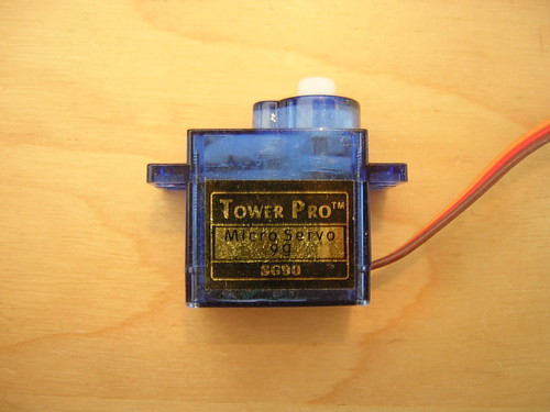
The Tower Pro/T-Pro SG-90 is a tiny and very (~$4) inexpensive hobby servo available from several online retailers. This How-To will show you how to modify one for continuous rotation.
Tools
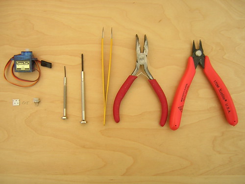
You'll need the following tools and supplies:
- Small Phillips screwdriver (#0)
- Small flathead screwdriver
- Tweezers
- Pliers
- Flush or diagonal cutter
- Soldering iron, solder, flux, and desoldering wick [not pictured]
- 1x Tower Pro SG-90 hobby servo
- 2x 2.2k 603 SMD resistors
The exact value of the resistors probably isn't important, as long as they are the same.
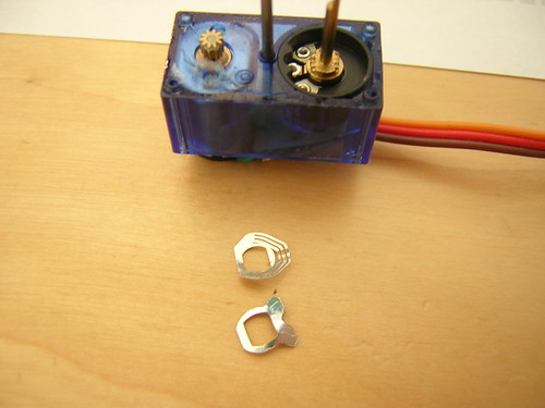
Disassembly
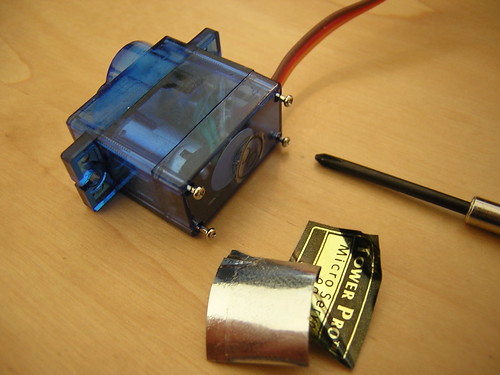
To disassemble the servo remove the stickers on the sides and unscrew the screws on the bottom. The servo is made of three segments: the top cover, middle, and bottom cover. Remove the bottom cover and set it aside, then remove the top cover. Use your pliers to pull the top (output) gear off of the potentiometer shaft, then remove the gears. Keep track of which shaft each gear came from, as the bottom two gears look very similar.

Defeating Mechanical Stops
There are three mechanical stops that must be removed before the servo can turn freely. Two of them are in the potentiometer. Use a small screwdriver to pry the metal plates off of the potentiometer shaft.
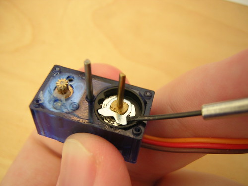
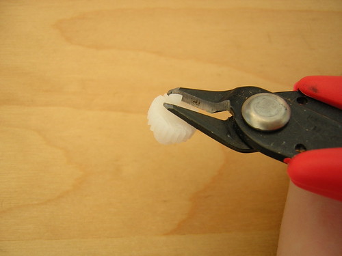
The third mechanical stop is a small nub on the bottom of the output gear. Use your flush cutter to remove it.
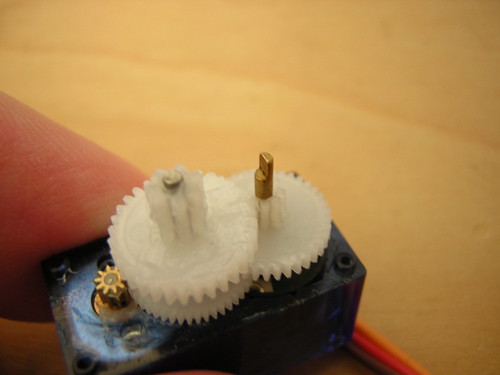
Reassemble the geartrain and put the top cover on. Note that the output gear sits on a D-shaped shaft; it must be pointing the right direction to go on.
Electrical
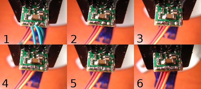
With the mechanical stops defeated, the servo must be tricked into turning the motor continuously. Lift the PCB up and remove the piece of plastic underneath it. Don't lose the plastic. Cut the three wires at the potentiometer. The wires are just tack-soldered to the top of the PCB, so heat each blob in turn and pull the wire out. Use the corner of a piece of solder wick to remove the solder from the middle pad. Apply flux. Pick up a resistor with tweezers and place it in between the left and middle pads. Heat the left pad, and push the resistor into the solder blob. Do the same with the other resistor and the right pad. Apply flux to the resistors and the middle pad, then place a dollop of solder between them. The joint should connect both resistors and the middle pad.
Reassemble the servo by putting the piece of plastic and the PCB back in place. Place the bottom cover on and screw in the four screws.