Retro LED Clock
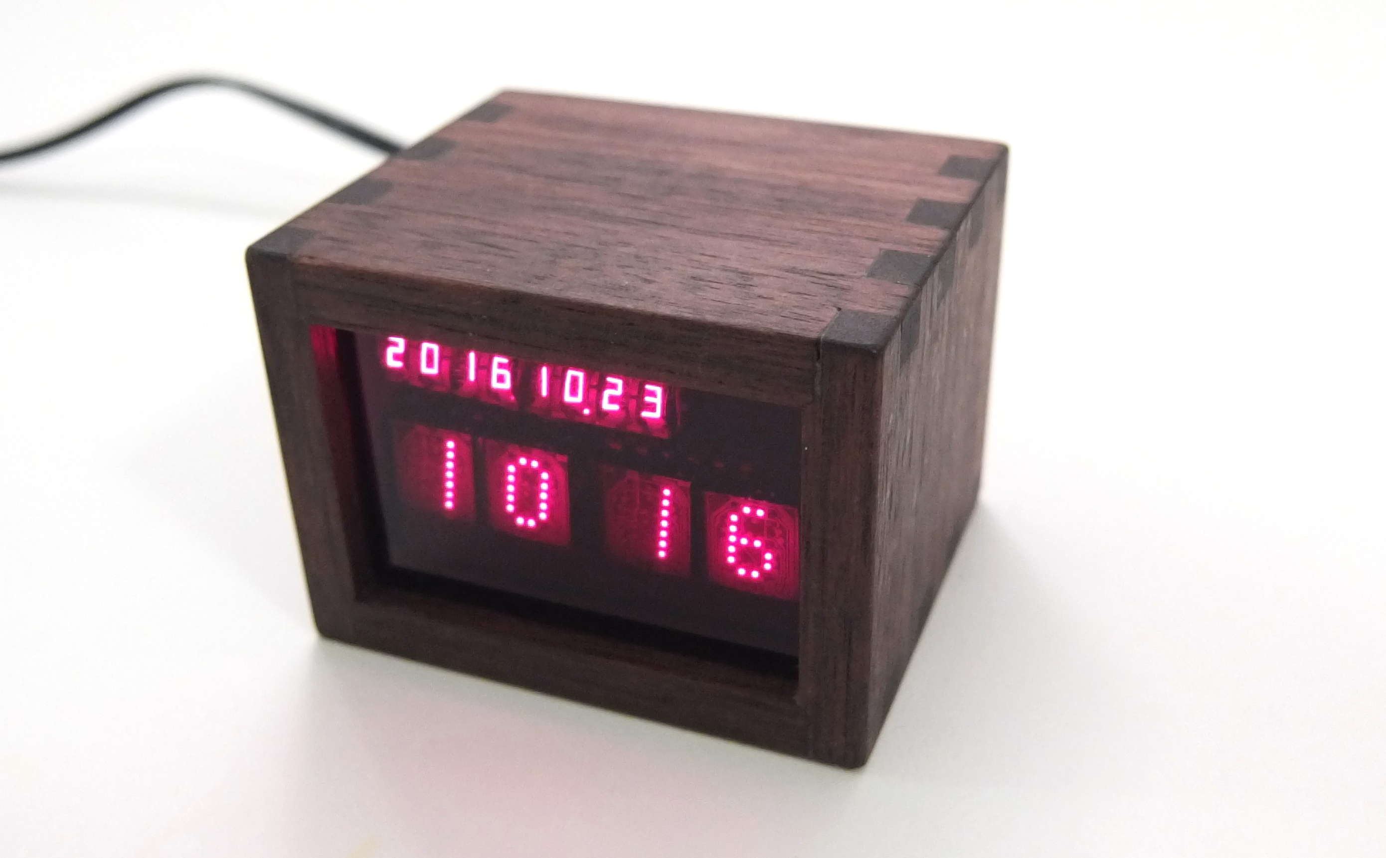
I really love the look of old Hewlett-Packard LED displays, so I used some to make a clock. This clock displays the time and date using dot-matrix displays and seven-segment "bubble" displays. Although they look pinkish in the photograph (since the color is outside the gamut of most monitors), the true color is a deep ruby red.
The time is shown with four HP 5082-7300 dot-matrix displays. This type has a partial grid of LED dies and a built-in decoder chip. The date is shown with two HP 5082-7414 four-digit seven segment "bubble" displays. These contain tiny digits with a magnifying lens, and were used in early HP calculators. A colon separates the time digits and indicates AM/PM (the lower dot only lights up in the afternoon). Light from the colon LEDs is sent to the front with light pipes made from heat-shrink tubing. Unfortunately, the viewing angle of the light pipes isn't very good.
The case of the clock was made from walnut by my friend Dylan Rathkamp. A laser-cut piece of red acrylic serves as the front window, and the PCB is mounted on a 3D-printed holder. The power jack (5V 1A) and buttons are mounted on the holder and connected with wires. For simplicity, all connections to the PCB are made through the microcontroller programming header.

An Atmel Atmega88PB microcontroller runs three interrupt threads, along with a main loop, to operate the clock. The interrupt threads are driven by timer peripherals, and handle display multiplexing, colon LED pulse-width modulation, and 1Hz time counting. The main loop updates the time digits from the system time and allows the time to be set with the buttons.
The date digits are multiplexed at 1kHz, with one digit on at a time. Since the time data lines are shared with the date display, the same interrupt handles both. To modulate brightness, the displays are turned on by the overflow interrupt of the controlling timer, then turned off by an output compare interrupt.
During the night, the display can be dimmed to be less intrusive. I originally wanted this to be automatic, with the ambient light level measured by timing the discharge rate of a photodiode. However, this wasn't sensitive enough, so I just used one of the buttons to switch between bright and dim modes.
The dot-matrix time displays dissipate a large amount of power (up to 1W each). Curiously, a significant fraction of this is from the decoder IC rather then the LEDs. In a 20°C room, the inside of the case reaches approx. 65°C, according to the AVR's internal thermometer.

