NXT Motor Driver

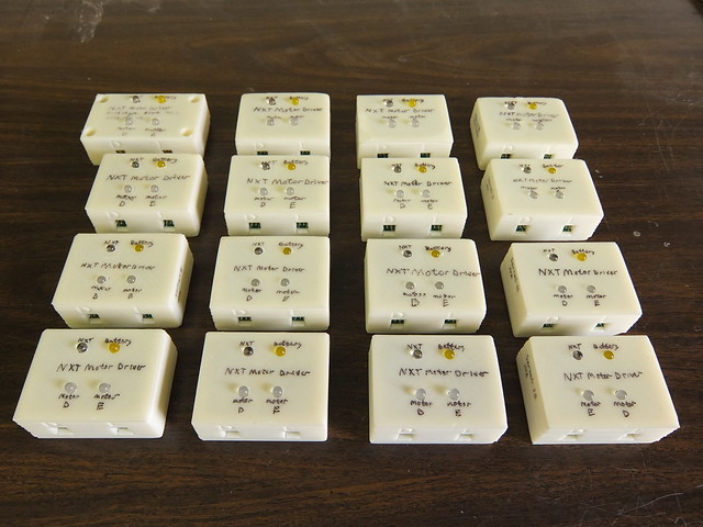
For my high school senior project, I designed and built 16 motor drivers for a robotics class. The class was using Lego NXTs, which can control 3 motors, but the teacher wanted to expand their capabilities with additional motors. Each motor driver controls two RCX DC motors from an NXT sensor port, with power provided by a small 12V battery.
Design
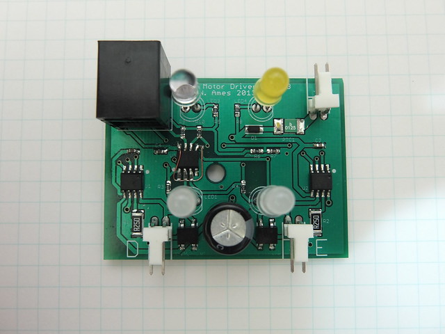
To simplify the design, I used an I2C port expander (an NXP PCA9536) instead of a microcontroller. At the time, I knew little about the I2C protocol, and wasn't confident in my ability to write robust firmware on a tight schedule.
The port expander controls two Allegro A4953 motor drivers. Although each chip can supply 2A of current, the current is limited to 400mA to prevent damage to the RCX motors.
The front of each device has four LEDs: two red/green bicolor LEDs indicate the direction of each motor, and two LEDs indicate whether the battery and NXT are connected.
The cases were designed in Blender, and printed on my Makerbot Thing-o-Matic.
Debugging
While the final PCBs were en route from the manufacturer, I discovered that the pull-up resistors inside the port expander were inadequate to hold the motor driver signal lines high. This caused motors to sometimes start turning when the device had not been initialized. To correct the problem, I soldered four external pull-up resistors to the leads of each port expander. This could have been avoided if I'd read the datasheets more carefully, and after making more than 150 fiddly solder joints I'll never make that mistake again.
Files
The design files are available here: NXT Motor Driver.zip. Everything except the RobotC library is licensed under Creative Commons Attribution v3. The RobotC library is placed in the Public Domain. Please note that the pull-up resistor bug has not been corrected on the board layout. You should do that if you plan on actually using the design.