Tiny Photopopper

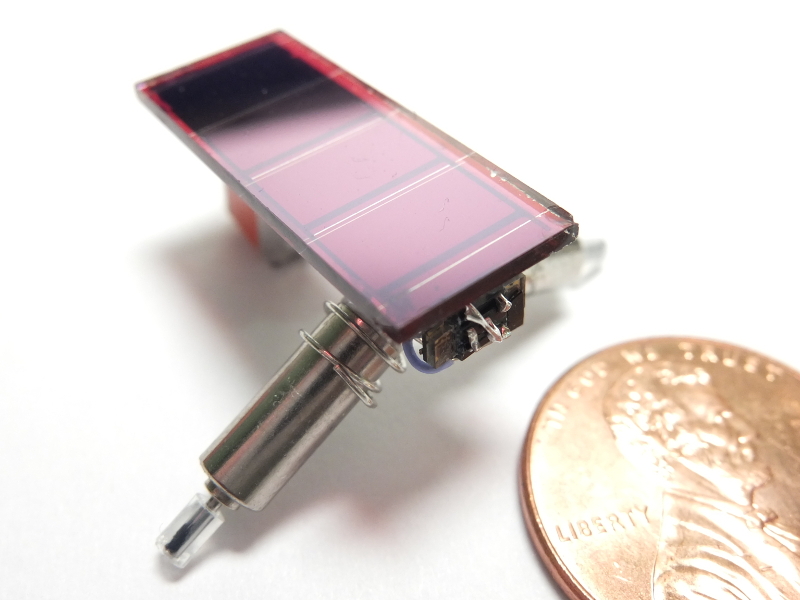
This is a small photopopper made from a calculator solar cell and two tiny motors. Photopoppers are a variety of BEAM robot, a style of hobby robotics that emphasizes simplicity and salvaged parts.
In a well-lit room, the solar cell (a Sinonar SS2510-S-B26) produces 2V at approximately 1μA, nowhere near enough to run a motor directly. Instead, power from the solar cell is stored in a capacitor, then released when enough energy is available for a small movement. This type of circuit is known as a solar engine.
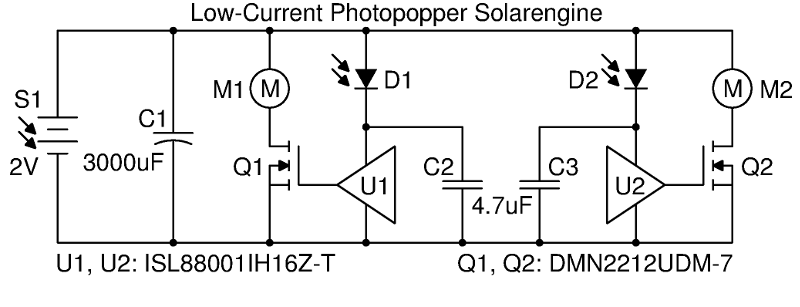
To sense when enough energy has been accumulated, a voltage monitor integrated circuit is used. Most voltage monitor ICs, including the Panasonic MN1381 commonly used in solar engines, consume at least 1μA, leaving no current to charge the storage capacitor. An exception is the Intersil ISL88001, which requires only 160nA. However, the ISL88001 has a very small hysteresis compared to the MN1381 (~20mV vs. 100mV), so the standard Miller solar engine circuit must be modified.
The Miller engine uses bipolar transistors to control the robot's motors. Replacing them with MOSFETs allows the circuit to operate with the ISL88001's small hysteresis. (The Miller engine isolates the voltage monitor with a capacitor and diode, causing the monitor to stay on as the main supply drops to 0V. A bipolar transistor requires current to operate, which quickly discharges the capacitor below the ISL88001's hysteresis threshold. MOSFETs, by contrast, requires no current to remain on.) I used a DMN2215UDM-7, a dual n-channel MOSFET that works at very low gate voltages.
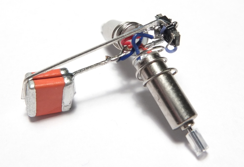
The main storage capacitor is composed of two 1500μF tantalum capacitors in parallel. They seem to have slightly higher leakage than an equivalent electrolytic capacitor, but the robot still works fine in a brightly lit room.
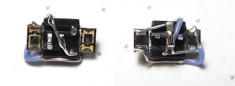
Both the solar engine and mechanical structure were freeform soldered. The solar engine is a sandwich composed of the dual MOSFET in between the two voltage monitors, with the eye photodiodes glued to either side of the stack. To save space, I omitted a balancing potentiometer and used a piece of electrical tape over one photodiode to tune the robot's response to light. (Without balancing, a photopopper will tend to turn in only one direction.)


